IEC 61499
Introduction
IEC 61499-1 defines the architecture for distributed systems. In IEC 61499 the cyclic execution model of IEC 61131 is replaced by an event driven execution model. The event driven execution model allows for an explicit specification of the execution order of function blocks. If necessary, periodically executed applications can be implemented by using the E_CYCLE function block for the generation of periodic events.
IEC 61499 enables an application-centric design, in which one or more applications, defined by networks of interconnected function blocks, are created for the whole system and subsequently distributed to the available devices. All devices within a system are described within a device model. The topology of the system is reflected by the system model. The distribution of an application is described within the mapping model. Therefore, applications of a system are distributable but maintained together.
Like IEC 61131-3 function blocks, IEC 61499 function block types specify both an interface and an implementation. In contrast to IEC 61131-3, an IEC 61499 interface contains event inputs and outputs in addition to data inputs and outputs. Events can be associated with data inputs and outputs by WITH constraints. IEC 61499 defines several function block types, all of which can contain a behavior description in terms of service sequences:
Service interface function block – SIFB: The source code is hidden and its functionality is only described by service sequences;
• Basic function block - BFB: Its functionality is described in terms of an Execution Control Chart (ECC), which is similar to a state diagram (UML). Every state can have several actions. Each action references one or zero algorithms and one or zero events. Algorithms can be implemented as defined in compliant standards.
• Composite function block - CFB: Its functionality is defined by a function block network.
• Adapter interfaces: An adapter interface is not a real function block. It combines several events and data connections within one connection and provides an interface concept to separate specification and implementation.
• Subapplication: Its functionality is also defined as a function block network. In contrast to CFBs, subapplications can be distributed.
To maintain the applications on a device IEC 61499 provides a management model. The device manager maintains the lifecycle of any resource and manages the communication with the software tools (e.g., configuration tool, agent) via management commands.
4Diac framework
The PLC functionality in the WCC Lite is implemented using Eclipse 4diac framework, consisting of the 4diac IDE and the 4diac FORTE runtime. The system corresponds to IEC 61499, an extension of IEC 61131-3. For more in-depth instructions and function block reference please see the 4diac manual - this document is merely a quick start guide that emphasizes the specifics of tailoring the applications to run on the WCC Lite.
The 4diac IDE application is used to model logic sequences. An output file, *.fboot, is then generated and either loaded into the runtime for debugging purposes (functionality available from within the IDE), or uploaded into the controller for normal use via web interface.
During debugging, the output logic is executed directly in the runtime. Any logic loaded during debugging will be discarded after a reboot of the controller. Logic applications for regular use should be uploaded via the web interface.
It is possible to run multiple tasks at once. These tasks can either be implemented in the same screen or split into separate tasks. Please note, however, that all elements should have unique names, even between different tasks. As of 4diac IDE 1.11.3 this is not enforced between separate apps, however, 4Diac runtime application rejects such file purely because of naming issues.
The 4diac FORTE runtime is able to execute the aforementioned fboot files containing the logic. The FORTE runtime can be run on both the WCC Lite and a PC for debugging purposes. The runtime is integrated to interact with the REDIS database.
Example project
The best way to understand basics of 4Diac and WCC Lite collaboration is through an example project. This user manual intends to show the pieces needed to run PLC applications on WCC Lite. It is not intended to be definitive guide on how to use 4Diac IDE or how to interpret IEC 61499 standard.
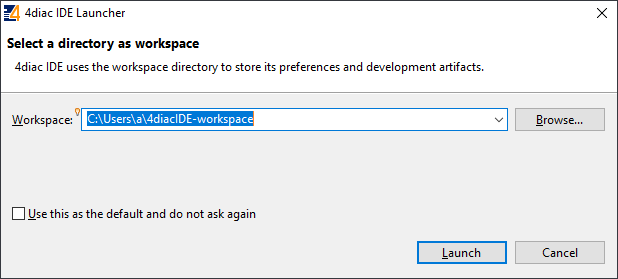
During (at least) the first start of the IDE user will be asked to select a directory for the workspace as in Figure. Workspace is used to save files needed for projects.

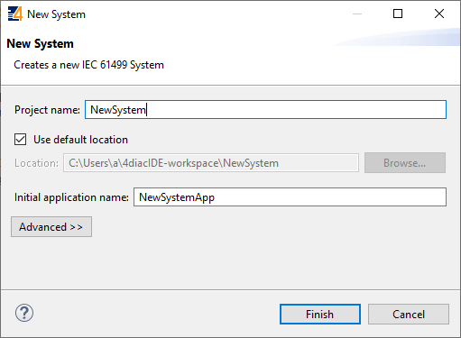
After that a user should be met by the welcome window as in Figure 20. If such window is not shown, one can create create project by selecting File->New->Project and filling in the required fields (figure 21).
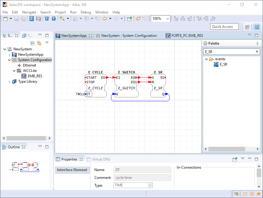
To create a simple application, simply drag and drop objects from the palette to the canvas and wire them accordingly. Event trigger and data pathways cannot be connected to one another. Displayed below is an example of a simple blinker application (figure 22).
Having less wiring by connecting several signals to same subnet as PCB designer (such as Altium Designer) as of 4Diac IDE 1.11.3 is not supported. However, if some parts are used frequently, it is highly advised to have less wiring by simply compiling several elements into a subapplication. For this, you would have to select elements to be grouped, press right key and select New Subapplication. You can later change names of such elements and its pins.
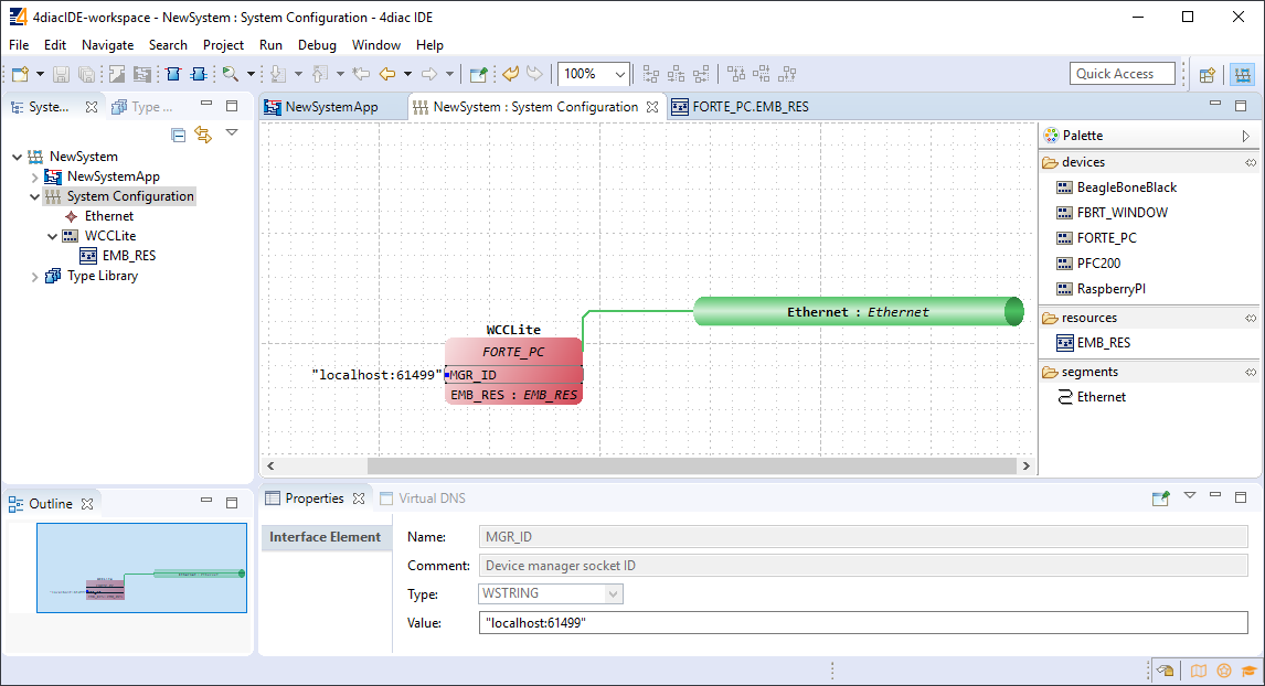
In the System Configuration section, drag and drop a FORTE_PC device, an Ethernet segment and link them (figure 23). For debugging in the local (PC) runtime, leave the address ”localhost:61499”. For testing on a WCC Lite, enter the IP address of the device, along with the port number (which by default is 61499 as well).
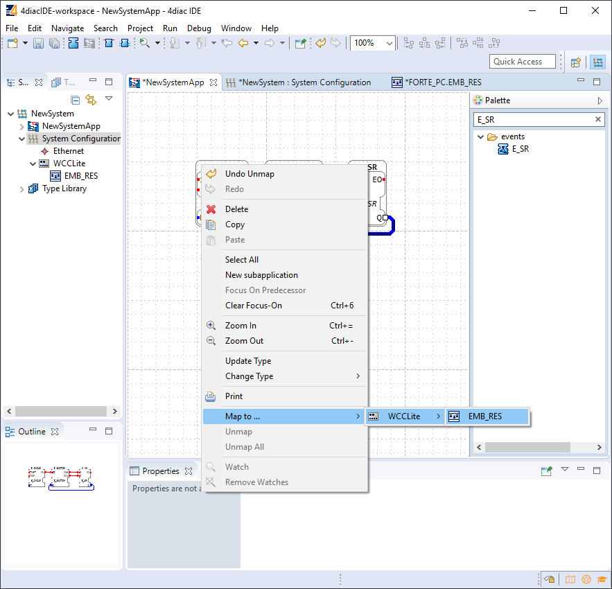
In order to deploy the application, the circuit needs to be mapped to the controller. For a non-distributed application (distributed application cases will not be discussed in this chapter), all the FBs of the application need to be selected and mapped to the configured controller as shown in figure 24.
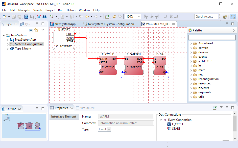
To start the application execution, an initial trigger needs to be present. For a non-distributed application, the initial event trigger needs to be wired from the START function block in the resource section as shown in figure 25.
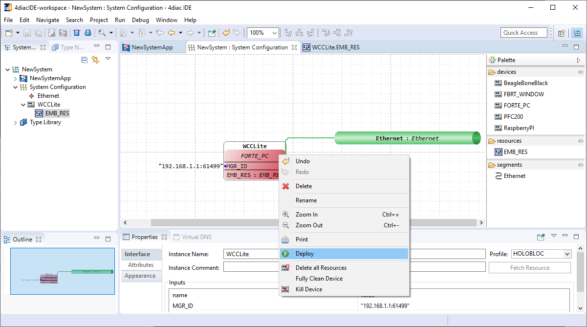
To deploy the application, go to the System Configuration tab and simply select ”Deploy” from the right-click menu of the controller device (figure 26). If a running application exist in the runtime, you may be asked whether you want to replace it. This will only overwrite the application in the memory and not the storage. If the controller is restarted, the old application will be loaded from the
non-volatile memory of the controller.
Read more: Configuring data endpoints